
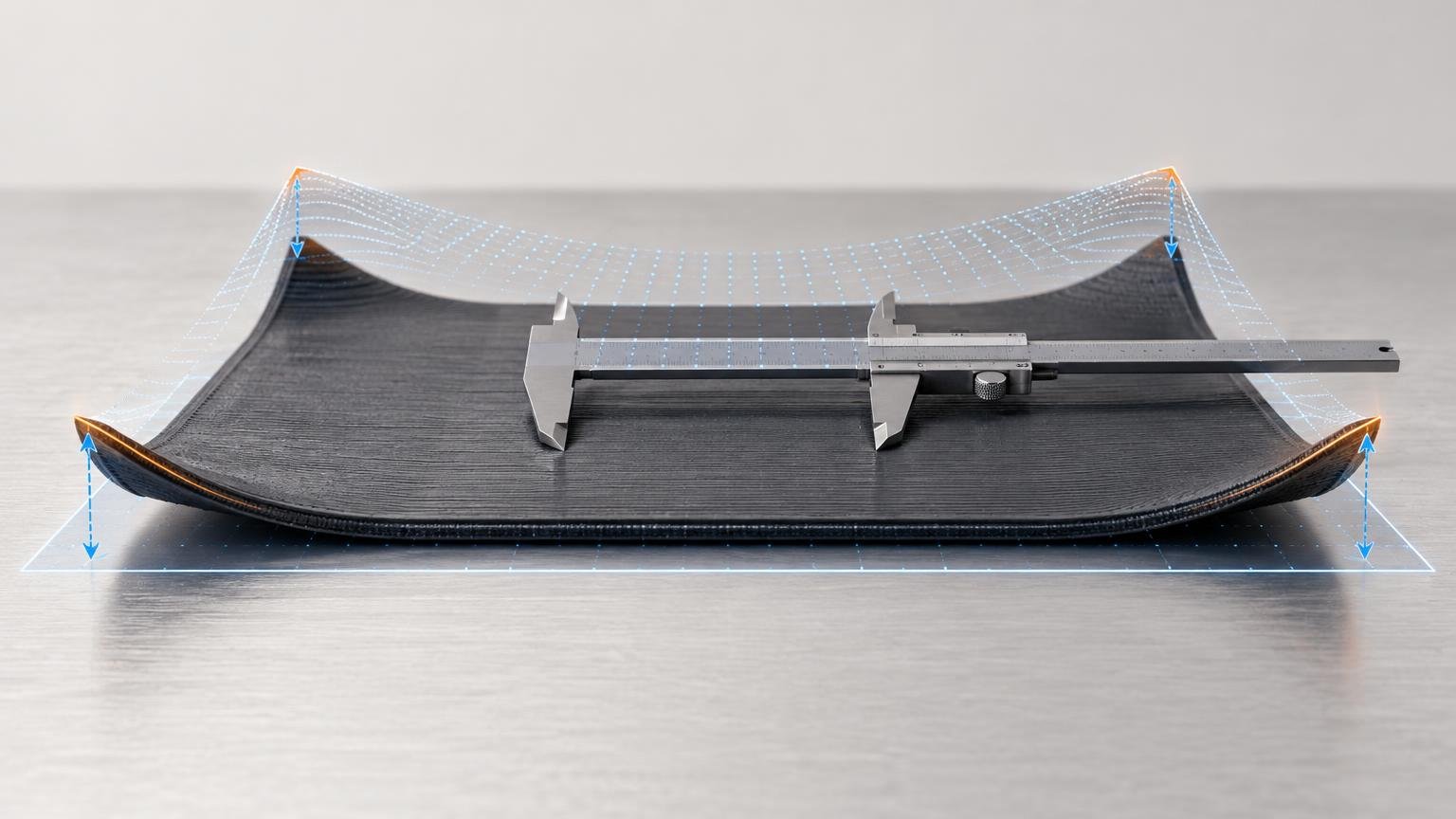
Why an FDM Part Can Measure Correctly in the Middle but Curl at the Corners
A part that measures correctly through the middle but lifts at one or more corners does not primarily have a scaling problem. It has a local geometry problem. The center measurement may be accurate while the base is no longer flat, the corner features have shifted, and the part rocks or fails to mate with another component.
Do not correct that pattern by scaling the entire model. First map where the error occurs, record the print conditions, and determine whether you are seeing corner warping, uniform material shrinkage, or a machine-calibration error. Each failure needs a different correction.
Local curl and uniform dimensional error are different failures
Corner lifting occurs when contraction and internal stress overcome adhesion to the build surface. A corner can rise from the plate and pull nearby walls inward or upward while much of the part remains close to its nominal dimensions. Prusa and Polymaker both describe warping as a cooling- and shrinkage-related deformation that can affect a corner or a larger area of the print. Prusa’s warping guide outlines the visible lifting pattern, while Polymaker discusses the material stresses behind it.
Uniform shrinkage looks different. If several comparable dimensions across the cooled part are consistently undersized by a similar proportion, material shrinkage or process calibration becomes a more plausible explanation. Cura’s Scaling Factor Shrinkage Compensation changes X, Y, and Z equally before slicing. That can address a repeatable whole-part contraction, but it cannot straighten a corner that has bent out of plane.
Machine geometry is another separate category. Prusa’s XYZ calibration, for example, addresses perpendicularity and skew in the motion system. It does not remove material stress or restore a corner that detached from the build plate.
Measure the shape, not just one convenient span
One caliper reading through the middle can answer whether that particular span is close to nominal. It cannot establish that the base is flat or that dimensions remain correct near every corner. Use the measurement method in the guide to measuring FDM prints with calipers and add a simple location map for this diagnosis.
At minimum, record the following before changing a setting:
- CAD nominal dimensions and the drawing revision or exported model used
- Material type, manufacturer, product name, color, and relevant storage or drying condition
- Printer, nozzle diameter, build surface, layer height, part orientation, and complete slicer profile
- Footprint geometry, including long edges, thin corners, holes, ribs, bosses, and sharp changes in section
- X and Y measurements at the center and near each end or corner, taken at defined heights
- Overall Z height at multiple locations when the geometry permits it
- Which corners lifted and the measured or visually observed lift at each location
- Whether the cooled part rocks on a known-flat reference surface
- First-layer appearance, brim or raft use, cooling settings, enclosure state, and possible drafts
Repeat readings rather than trusting the first caliper contact. A CF/PETG dimensional-accuracy study measured repeatedly in each axis and averaged its readings; that protocol is specific to the study, but the underlying lesson is useful: a single reading is weak evidence for characterizing a part’s dimensional behavior.
A practical measurement map might label the left, center, and right positions along a long rectangular part. If the center width matches CAD but both end widths differ and the base rocks diagonally, that pattern points toward local deformation. If all three widths are consistently small while the base remains flat, investigate shrinkage, extrusion behavior, and calibration instead.
Compare the correction to the observed error pattern
For corner lifting, start with the first layer and thermal environment. Prusa and UltiMaker troubleshooting documentation emphasizes build-surface condition, first-layer setup, controlled cooling, stable ambient conditions, suitable material profiles, and geometry-dependent aids such as brims, draft shields, or enclosures. These are a family of diagnostic options, not a universal recipe.
Check the basics in a controlled order. Confirm that the build surface and first layer provide consistent adhesion. Remove direct drafts. Review part-cooling behavior, particularly during the lower layers. Then consider whether a brim, enclosure, or less warp-prone orientation is appropriate for the material and footprint.
Avoid copying one bed-temperature number into every profile. Prusa’s ASA guidance specifies at least a 100 °C bed and an enclosure for its documented ASA process, but that is not a general setting for PLA, PETG, nylon, or every printer and surface. Excessive fan speed can also contribute to lifting and weaker layer adhesion.
A warmer build plate can reduce contraction near the base, but UltiMaker also notes that excess heat may contribute to bottom-layer sag and elephant’s foot. First-layer horizontal-expansion compensation can then alter the dimensions you measure near the build plate. Fixing corner lift by creating a swollen base is not dimensional success.
Material and geometry can change the answer
Sharp corners, broad footprints, uneven wall sections, and long straight edges can concentrate shrinkage stress differently. Material behavior matters as well. Polymaker notes additional crystallization-related shrinkage in semi-crystalline materials such as nylon and declines to give one standard nylon dimensional-change value because geometry, size, and infill density affect the outcome.
Published experiments should be read with the same restraint. One experimental study of FDM warpage used ABS rectangular plates on a Stratasys Dimension Elite and compared 0.178 mm and 0.254 mm layers while varying specimen dimensions. Its findings describe that material, geometry, machine, and test setup; they do not supply a universal anti-warp layer height.
Likewise, a PLA parameter study reported an optimized combination involving a 0.1 mm layer height, six perimeters, 20% infill, 70 mm/s speed, a 220 °C nozzle, a 70 °C bed, and a 90-degree orientation. Those numbers belong to its model and experimental design, not to every curled PLA part. The published study is useful for understanding parameter interaction, not for bypassing diagnosis.
Validate the correction with the same measurement map
Change one meaningful factor or one tightly related group of factors, reprint under documented conditions, allow the part to cool, and repeat the same location-based measurements. A smaller test coupon can reduce material use, but it should preserve the troublesome footprint, corner geometry, orientation, wall behavior, and first-layer conditions. The method in designing a calibration part for fit testing can help keep that comparison relevant to the final component.
Only consider global scaling after the part prints flat and repeated measurements demonstrate a consistent proportional error. If the remaining error is axis-specific or varies by feature, follow a targeted dimensional-accuracy calibration workflow instead of treating scale as a universal adjustment.
The final acceptance test should match the requirement: flatness on the intended mounting surface, alignment of fastener locations, clearance at the actual interface, or repeatable movement in an assembly. NIST’s discussion of additive-manufacturing part qualification treats machine capability, material properties, metrology, test artifacts, and acceptance criteria as connected parts of qualification. A prototype that fits once is useful evidence, but it does not by itself prove suitability for safety-critical service.
The decisive distinction is spatial. A uniform error follows the part; corner curl is concentrated deformation. Record where the geometry failed, stabilize the print so it remains flat, and then calibrate any repeatable dimensional error that remains.
Frequently Asked Questions
Does an accurate center measurement mean the whole part is dimensionally accurate?
No. It confirms only that measured span. A lifted corner can disturb flatness and nearby features while the center remains close to nominal.
How can I distinguish corner curl from uniform shrinkage?
Measure comparable dimensions at the center and near each end or corner. Local differences combined with rocking or visible lift indicate deformation; consistently undersized dimensions on a flat part make uniform shrinkage or calibration more plausible.
What should I record before changing print settings?
Record the CAD revision, material identity and condition, printer and nozzle, build surface, orientation, footprint geometry, slicer profile, first-layer appearance, cooling and enclosure conditions, lifted locations, and measurements taken at defined positions.
Should I scale a model to compensate for curled corners?
No. Equal-axis shrinkage compensation changes the whole model and cannot straighten a corner bent out of plane.
What should I check first when corners lift?
Check build-surface condition and first-layer consistency, remove drafts, review lower-layer cooling, and then evaluate material-appropriate options such as a brim, enclosure, draft shield, or different orientation.
Is there one bed temperature that prevents FDM warping?
No. The suitable temperature depends on the material, printer, surface, and geometry. Prusa’s documented ASA process specifies at least a 100 °C bed and an enclosure, but that is not a universal setting for other materials or machines.
How do I verify that the correction worked?
Let the reprint cool, repeat the same location-based measurements, and test the actual requirement such as mounting-surface flatness, fastener alignment, interface clearance, or repeatable movement. One successful fit does not establish suitability for safety-critical service.
References
- Warping | Prusa Knowledge Base
- support.ultimaker.com
- Warping | Polymaker Wiki
- Experimental investigations of process parameters on dimensional accuracy for FDM printed CF/PETG parts – Guoqiang Tian, Kai Wu, Sensen Gao, Guang Zeng, Jianwei Liu, 2025
- support.ultimaker.com
- support.ultimaker.com
- XYZ Calibration (MK3/MK3S/MK3S+) | Prusa Knowledge Base
- Warping | Polymaker Wiki
- support.ultimaker.com
- ASA | Prusa Knowledge Base
- Moisture Conditioning | Polymaker Wiki
- Warpage of FDM parts: Experimental tests and analytic model – ScienceDirect
- Parametric Investigation and Optimization to Study the Effect of Process Parameters on the Dimensional Deviation of Fused Deposition Modeling of 3D Printed Parts – PMC
- Additive Manufacturing Part Qualification | NIST
- Optimization of fused filament fabrication process parameters under uncertainty to maximize part geometry accuracy | NIST