FDM Calibration, Print Tolerances and Functional Parts
Practical guidance for FDM users designing parts that must fit, move, assemble, and meet dimensions reliably. Explore calibration, tolerances, geometry, strength, and functional features to help prove a print works, not merely looks correct on screen.
Make the Print Prove the Design
FDM calibration is useful only when it improves the part that leaves the build plate. A clean cube or smooth surface does not answer whether a bore accepts its shaft, two sections slide together, or a bracket lands on the required dimensions. 3D Printed Proof focuses on that gap between the digital model and the physical result, with practical coverage for FDM users designing parts that must fit, move, assemble, or hold their intended geometry. It is for decisions where a small dimensional difference, clean motion, or repeatable assembly determines whether the model is useful.
The central question is simple: did the print meet its dimensional and functional requirement? Answering it usually requires more than changing one slicer value. Material behavior, extrusion, first-layer conditions, feature geometry, orientation, wall construction, cooling, and measurement method can all affect the result. This publication covers how to separate those variables, choose a useful calibration target, and judge the finished part against the requirement that matters instead of relying on appearance alone. The aim is to make each adjustment answer a question, rather than treating calibration as a collection of disconnected ritual prints.
Expect focused guidance on undersized holes, dimensional error, clearance, fit classes, thin walls, orientation effects, calibration pieces, threads, inserts, and other functional features. Exact values need context, so useful comparisons account for relevant conditions such as nozzle, material, layer height, machine, print orientation, and measurement method. A clearance that works in one setup is a starting point for validation, not a universal design rule. The goal is a repeatable decision process rather than an unexplained number.
Find the Right Starting Point
Start with Calibration & Accuracy when the printer is missing dimensions broadly, holes are consistently small, first-layer expansion affects edges, or the measurement itself needs a better method. Move to Fit & Tolerances when two printed parts must slide, press together, rotate, align, or assemble with controlled play. The distinction matters: general dimensional correction addresses process behavior, while fit work defines the intentional relationship between mating features and verifies that relationship under the selected print conditions. Start with the symptom, then identify the feature and condition that define success.
Use Strength & Walls when the primary requirement is resisting a load, maintaining a thin section, or choosing wall construction that remains dependable. Geometry & Orientation is the better route when shape and build direction change the outcome, including bores, overhangs, mating faces, anisotropic behavior, and identical models that print differently after rotation. These areas overlap, but beginning with the failed requirement keeps the investigation focused and makes any follow-up comparison more useful. It also makes it easier to decide which variable deserves attention first.
Choose Functional Features for threads, inserts, pegs, sockets, hinges, calibration coupons, and other details whose purpose depends on assembly or motion. If the cause is unclear, begin with dimensional calibration guidance, establish a measurable baseline, and then follow the category tied to the feature that failed. Bring the design requirement with you: nominal dimension, acceptable variation, intended type of fit, direction of load, or required movement. A stated requirement makes it possible to judge the printed result without mistaking visual quality for functional success. That is the shortest path to a useful next test.
Latest from 3D Printed Proof
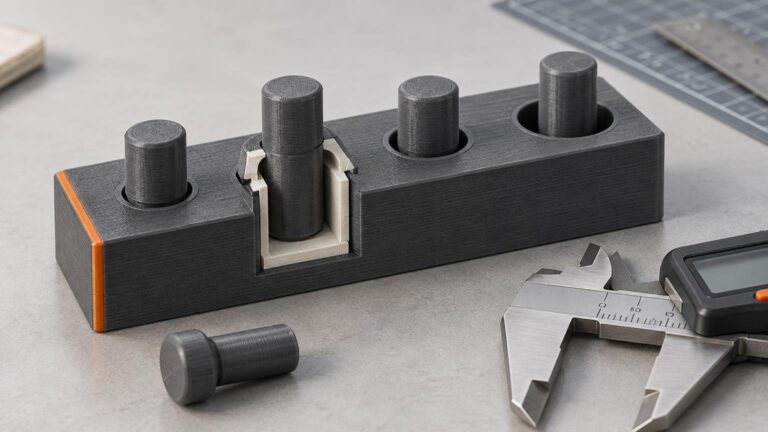
How to Design a Simple Calibration Part for Fit Testing
A useful fit-test part reproduces the real joint, varies one clearance at a time, and is printed under the same conditions as the final component.
Read more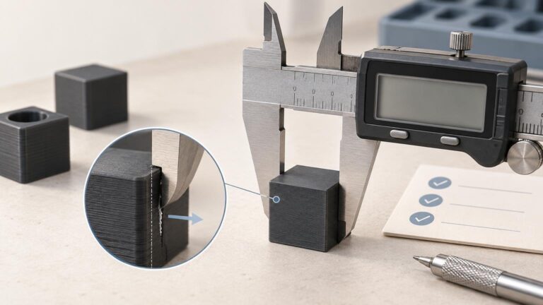
How to Measure an FDM Print With Calipers Without Misreading the Result
A practical method for measuring cooled FDM parts, documenting repeated readings and separating real dimensional error from local print defects.
Read more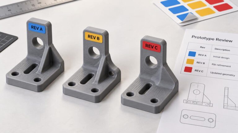
How to Label 3D-Printed Prototype Revisions for a Client Review
Build a traceable labeling system for client prototypes, choose between individual stickers and sticker sheets, and keep labels away from functional surfaces.
Read more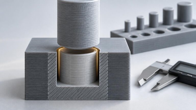
3D-Printed Peg and Socket Tolerances: How Much Gap Do You Need?
There is no universal peg-and-socket clearance for FDM parts. Define the gap correctly, print a calibration coupon under final conditions, and verify the fit.
Read moreMeasure the Requirement, Not the Appearance
Dimensional accuracy is not a single score that makes every feature correct. External dimensions, internal openings, first-layer edges, vertical walls, bridges, and mating surfaces can respond differently to the same process. A useful diagnosis identifies where the error appears, whether it is consistent, and whether it changes with feature size or direction. That distinction helps separate broad calibration problems from geometry-specific behavior and prevents one compensating adjustment from creating a new error elsewhere. A part can be acceptable on one dimension and unacceptable at its functional interface, so each result needs to be read in context.
Functional parts also require tradeoffs. A tighter fit may improve location while increasing assembly force or sensitivity to process variation. A thicker wall may resist one load while adding material or changing how the feature cools. A different orientation may improve strength in the load direction while reducing bore quality or altering a mating face. Coverage here keeps those competing effects visible so a recommendation explains not just what to change, but what the change may cost. The right choice depends on the requirement, not on a setting that appears universally stronger or more accurate.
The practical endpoint is validation with a representative feature or part. Define the important dimension, motion, load path, or assembly condition before tuning. Measure with a method suited to that requirement, record the relevant print conditions, and change one meaningful variable when possible. Then confirm the result where it will actually be used. That approach turns calibration from an open-ended search for perfect settings into a bounded process for deciding whether a printed design is ready, needs compensation, or should be revised. Validation closes the loop.
Frequently Asked Questions
What does 3D Printed Proof cover?
The publication covers FDM calibration, dimensional accuracy, print tolerances, wall construction, orientation, geometry, and functional printed features.
Who is this publication for?
It is for 3D-printing users designing parts that must fit, move, assemble, or meet dimensions reliably.
Why can the same clearance produce different results?
Fit can change with material, machine, nozzle, layer height, orientation, feature geometry, process settings, and measurement method. Empirical clearance values should be treated as test-specific unless broader evidence supports them.
Where should I start with a part that does not fit?
Define the failed requirement first, then check whether the issue is broad dimensional accuracy, a mating-feature tolerance, first-layer distortion, geometry, orientation, or another functional detail.