How Printable Terrain Designers Should Build Calibration Pieces Into a System
Printable terrain designers should treat calibration pieces as part of the terrain system, not as optional cubes placed beside it. A useful test piece reproduces the actual connector, floor edge, wall position and print orientation that must work in the finished assembly. It should tell the user whether to proceed, adjust a setting or investigate a specific failure before committing hours and material to a larger build.
That is a different job from proving that a printer can produce a nominal 20 mm block. NIST describes additive-manufacturing test artifacts as tools for assessing system performance through measurable geometric characteristics, with the relevant machine settings and process parameters documented. The same principle applies here: test the characteristics that determine whether the terrain functions as a system. NIST’s additive-manufacturing test artifact guidance provides the broader measurement framework.
Make the calibration piece part of the product architecture
The calibration file should be designed alongside the connectors and tiles, not after the terrain set is complete. When the connection standard changes, its calibration piece should change with it. When separate file variants use different wall arrangements, bases or print orientations, the designer should identify which variant each test represents.
This approach is visible in terrain ecosystems built around standardized interfaces. Printable Realms’ FDM-oriented modular terrain system, for example, emphasizes compatible connection points and physical checks of connector fit, wall sturdiness and miniature-supporting surfaces. The important lesson is structural: compatibility depends on more than the connector’s nominal dimensions.
Give every calibration file a revision identifier that can be matched to the terrain files it validates. A filename such as “connector-test-v2” is more useful than “test.stl,” but an embossed revision mark is better because it remains attached to the printed evidence. If a connector geometry changes without a corresponding test revision, users can pass an obsolete test and still fail the current system.
Test the complete functional interface
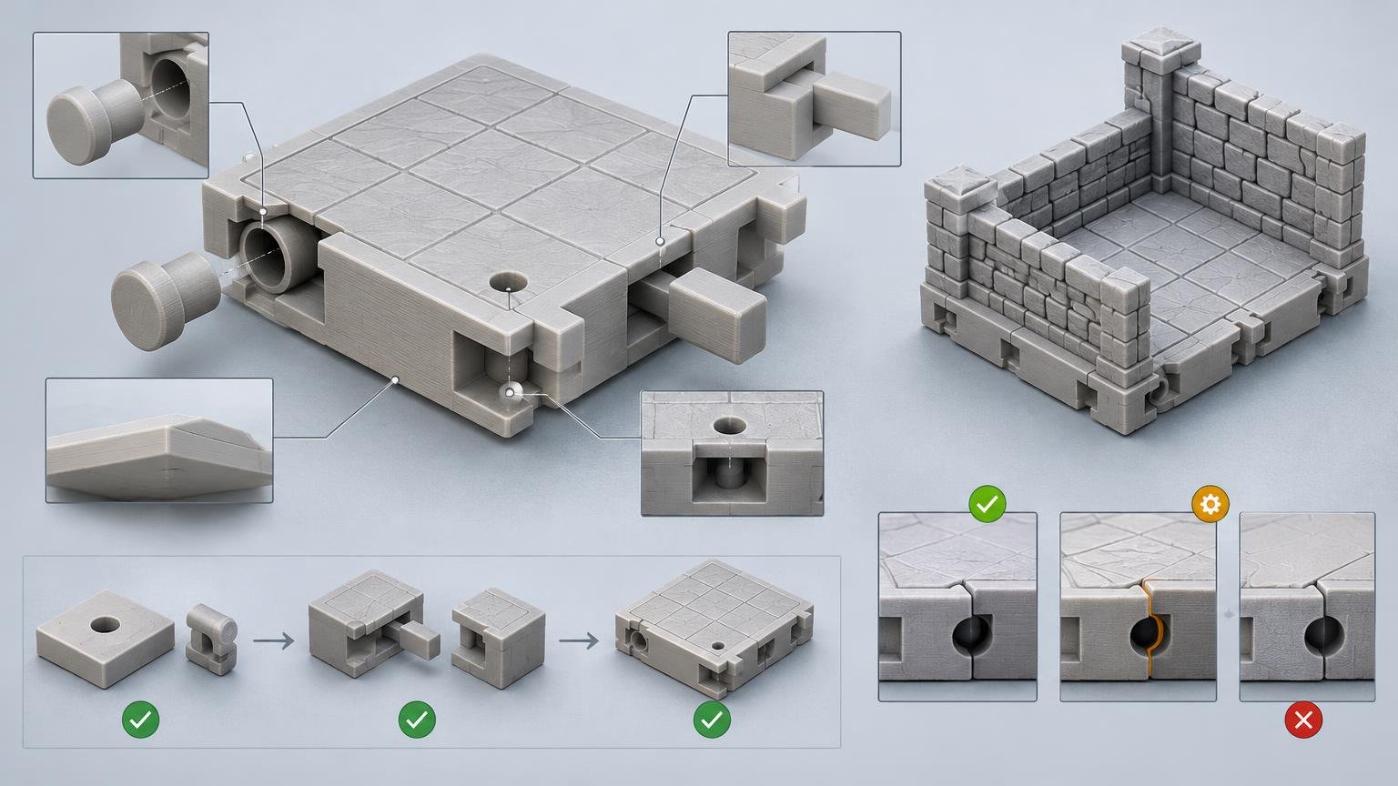
A connector coupon should include both sides of the joint and enough surrounding terrain to expose secondary problems. A clip that inserts successfully has not proved that two floor sections sit level, that the grid continues across the seam or that nearby walls remain correctly positioned.
Cross-system adapter guidance from Printable Realms distinguishes connector insertion from wider terrain compatibility. Its checks include seam and floor level, grid continuity, wall placement, vertical alignment, rocking on a flat surface, miniature movement and repeated handling. Those are useful design targets even when the calibration piece is intended for only one terrain family.
| Test element | What it should reveal | Useful pass condition |
|---|---|---|
| Connector pair | Insertion force, retention and removal | The intended fit is achieved without damage or excessive force |
| Joined floor edges | Seam width, level and rocking | The assembly sits stably with an acceptable transition |
| Grid or surface marks | Accumulated alignment error | Features continue across the joint as designed |
| Wall or corner reference | Interference near the connection | Adjacent geometry assembles without collision |
| Handling cycle | Wear, loosening and weak features | The joint remains functional after repeated assembly |
Keep the first coupon small, but do not simplify away the failure mechanism. If production tiles print flat on the bed with their connector openings near the first layer, the coupon should reproduce that condition. Rotating the test to obtain a cleaner result may validate a geometry the user will never actually print.
Use a progression rather than one overloaded model
One giant torture test creates ambiguous failures. A better system uses a short progression in which each piece answers a narrower question. The first stage establishes basic connector fit. The second verifies the interface in representative tile geometry. The final stage checks a small assembly under realistic handling.
- Print a compact connector pair with the production orientation and local wall thickness.
- Print two representative straight-edge terrain sections and inspect their seam, level and stability.
- Add a corner, wall or other feature that could interfere with the connection.
- Build a small multi-piece assembly and repeat insertion, removal and tabletop handling.
- Proceed to complex stairs, elevated sections or mixed adapters only after the simpler tests pass.
Starting with straight-edge connections before corners, stairs and elevated assemblies makes diagnosis easier. Printable Realms similarly recommends retaining the known file version and expanding from a small successful batch rather than beginning with a complicated mixed build.
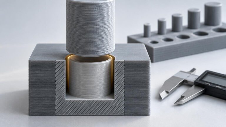
Designers can provide a separate clearance ladder when the system is expected to encounter a wide range of printers and materials. Each position should change one dimension only and carry a durable label. The nominal production interface should remain clearly identified; otherwise users may choose a loose sample without understanding that they have selected a modified geometry. Our guide to designing a calibration part for fit testing explains why varying one clearance at a time produces a more useful result.
Specify the conditions that make the result valid
There is no universal FDM clearance that works across every terrain system and printer. Prusa identifies model size, orientation, interlocking geometry, calibration, slicer settings and material properties as variables affecting mating tolerance. It also notes that bed-facing, supported and vertically printed surfaces do not produce equivalent results. Prusa’s design guidance for FDM parts is a useful reference for these constraints.
ISO/ASTM 52902 likewise frames geometric-capability assessment around a particular machine setup, process parameters and feedstock material. A passed terrain coupon therefore supports a defined print setup; it does not certify every machine or material. The ISO/ASTM test-artifact standard covers that setup-specific approach.
Package the calibration file with a short record sheet or readme that asks for the printer, nozzle diameter, material, slicer profile, layer height, orientation and file revision. It should also define the inspection method. “Fits” is too vague if one user means a removable slip fit and another means a joint that requires pliers.
Where dimensions matter, state what should be measured, where the caliper jaws should contact and whether the part must cool first. Repeated readings are more informative than reporting extra decimal places from one uncertain contact point. The practical method in measuring an FDM print with calipers can help users separate dimensional error from a rough seam or local defect.
Include first-layer effects in the test
Terrain bases make first-layer error especially important. Excessive first-layer squish can widen the bottom of a part and tighten a connector opening, close a seam or make adjacent tiles push apart. Prusa’s elephant-foot guidance explains that its compensation setting shrinks the first layer to counter this expansion.
A good terrain coupon gives users enough surrounding base to see this effect. Consider adding a small bottom-edge reference or a second connector positioned away from the bed. If the bed-adjacent interface binds while the elevated reference works, the evidence points toward first-layer expansion rather than a global scale error.
Define pass, adjust and fail outcomes
The calibration instructions should turn observations into decisions. “Looks good” is not a repeatable criterion. Define what the user should feel, measure or observe, then connect each result to a limited next step.
- Pass: the connector reaches its intended position, holds as designed, can be removed by the intended method and leaves the surrounding terrain aligned.
- Adjust: the geometry is intact, but fit or alignment falls outside the stated functional range. Change one relevant process variable and reprint the coupon.
- Fail: the part has warping, layer separation, incomplete walls, damaged connector features or another defect that prevents a meaningful fit assessment.
- Escalate: the connector passes alone but fails in representative terrain. Inspect first-layer shape, seams, wall interference and accumulated alignment rather than changing connector clearance immediately.
If the test includes thin tabs, labels or walls, keep them printable with the intended nozzle and extrusion width. Prusa notes that walls thinner than one nozzle perimeter are not printable; its 0.4 mm nozzle example uses an extrusion width of approximately 0.45 mm, subject to slicer settings. Decorative detail should never make the calibration object less representative or less reliable.
Use repetition to detect drift and weak interfaces
One successful connection proves only that one pair worked once. Supply duplicate interfaces when practical, or instruct users to print more than one coupon before a large production run. Repeated insertion and removal can expose burrs, weak clips, rapid loosening or material-sensitive retention that a single assembly misses.
NIST notes that repeating a test artifact after maintenance or recalibration can help track system performance and inform compensation. For terrain users, sensible repeat points include a nozzle change, new material formulation, major slicer-profile revision, printer maintenance or unexplained change in assembly behavior.
Designers should also keep the test quick enough that users will actually repeat it. A small coupon that isolates the decisive interface is more valuable than an impressive miniature structure that consumes nearly as much time as the first production tile. If basic dimensions fail before the terrain-specific checks begin, use a targeted FDM dimensional-accuracy calibration workflow and then return to the system coupon.
The calibration piece should answer a production question
The final design test is simple: after printing the calibration pieces, does the user know whether to start the terrain set? A strong system answers that question with representative geometry, controlled variants, named print conditions and explicit functional criteria.
Build the smallest artifact that reproduces the real risks, then validate those risks in stages. Test connector fit first, terrain alignment second and repeated assembly last. That gives users evidence about the part they intend to build—not merely reassurance that their printer can produce a tidy calibration cube.
Frequently Asked Questions
Why is a generic calibration cube insufficient for modular terrain?
A cube can reveal basic dimensional error, but it does not establish connector fit, seam quality, floor level, grid continuity, wall clearance or handling durability. The test should reproduce the terrain system’s functional interface.
How small should a terrain calibration piece be?
Make it as small as possible without removing the failure mechanism. Include both sides of the joint and enough surrounding floor, base or wall geometry to expose alignment, rocking and interference.
Should designers provide several connector clearances?
A labeled clearance ladder can help when users have varied printers and materials. Change one dimension at a time and identify the nominal production interface clearly so a loose variant is not mistaken for the standard geometry.
What print conditions should accompany a calibration result?
Record the printer, nozzle diameter, material, slicer profile, layer height, orientation, file revision and inspection method. Setup and process conditions determine what a passed coupon actually validates.
What does it mean if a bed-adjacent connector binds but an elevated reference fits?
That pattern points toward first-layer expansion rather than a global scale error. First-layer squish can widen the bottom of a print and tighten nearby mating features.
Should users scale the entire STL when a connector is too tight?
Not by default. Uniform scaling changes the connector, tile dimensions, grid spacing and wall positions together. Inspect first-layer shape, flow, calibration, seams, material behavior and shrinkage before changing the whole model.
When should terrain calibration pieces be reprinted?
Repeat the test after a nozzle change, new material formulation, major slicer-profile revision, printer maintenance or an unexplained change in fit. Repeated assembly can also reveal loosening, burrs and weak connector features missed by one successful fit.
References
- NIST Additive Manufacturing Test Artifact | NIST
- ISO/ASTM52902 Additive manufacturing — Test artefacts — Geometric capability assessment of additive manufacturing systems
- Modeling with 3D printing in mind | Prusa Knowledge Base
- Elephant foot compensation | Prusa Knowledge Base
- OpenLOCK-to-Dragonlock Adapter Clips Explained
- Printable Realms – printablerealms.com