
3D-Printed Peg and Socket Tolerances: How Much Gap Do You Need?
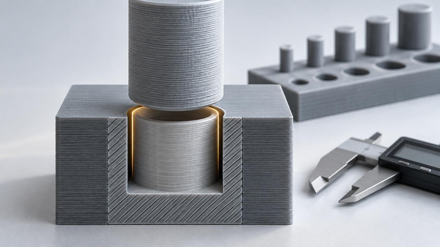
There is no universal value for 3d-printed peg and socket tolerances. For an FDM part, a useful starting experiment is to test 0.10, 0.20, 0.30, 0.40, and 0.50 mm of total diametral clearance, then select the fit that performs reliably under the final printing conditions. Those values form a calibration matrix, not a specification that every printer can reproduce.
The required gap depends on the joint’s job, the printer’s dimensional behavior, material, orientation, geometry, layer height, extrusion settings, and surface condition. Prusa likewise advises that mating-part tolerances vary with factors such as size, orientation, calibration, settings, and material; its suggested 0.3 mm starting measure for movable parts is guidance for initial testing rather than a universal rule.
This guide addresses FDM and FFF printing. Resin, powder-bed, and industrial processes have different error patterns and need their own validation. Even within FDM, a value established for a vertical PLA socket should not automatically be transferred to a horizontal PETG socket.
Define the clearance before choosing a number
People often use “tolerance” to mean the intentional gap between two parts, but tolerance and clearance are not the same. Clearance is the designed size difference between the socket and peg. Tolerance is the permitted variation around a dimension.
For a round joint, state whether the clearance is diametral or radial. Diametral clearance is the difference between the socket diameter and peg diameter. Radial clearance is the gap on one side, so it is half the diametral value.
For example, a 10.00 mm peg paired with a 10.20 mm socket has 0.20 mm diametral clearance and 0.10 mm radial clearance per side. If someone instead adds 0.20 mm on every side, the socket becomes 10.40 mm. That ambiguity is large enough to change a snug locating fit into a loose one.
| CAD peg diameter | CAD socket diameter | Diametral clearance | Clearance per side |
|---|---|---|---|
| 10.00 mm | 10.10 mm | 0.10 mm | 0.05 mm |
| 10.00 mm | 10.20 mm | 0.20 mm | 0.10 mm |
| 10.00 mm | 10.30 mm | 0.30 mm | 0.15 mm |
| 10.00 mm | 10.40 mm | 0.40 mm | 0.20 mm |
| 10.00 mm | 10.50 mm | 0.50 mm | 0.25 mm |
The table describes nominal CAD geometry. It does not predict the measured size of either printed feature. A nominal 10.00 mm peg may print oversize, while a nominal 10.20 mm socket may print undersize or out of round. The resulting physical clearance can therefore be much smaller than the model implies.
Match the gap to the required function
Do not classify a fit only as “works” or “does not work.” Write down what the joint must do. A peg that can be forced into a socket once may pass an assembly test but fail a requirement for repeated removal.
| Required behavior | What to verify |
|---|---|
| Easy assembly | The peg enters without tools, excessive force, or edge damage. |
| Repeated sliding | Motion remains smooth through the full travel and after several cycles. |
| Removable location | The joint limits unwanted movement but can still be separated as intended. |
| Friction retention | The peg resists the defined handling load without permanent damage. |
| Interference or press fit | Insertion force, retention, stress, and repeatability are acceptable across multiple samples. |
A clearance fit intentionally leaves a positive gap. A friction fit may rely on surface contact or slight elastic deformation. An interference fit intentionally makes the mating feature larger than the available opening. Printed interference fits are particularly sensitive to material stiffness, layer direction, wall construction, creep, and local dimensional error. Do not assign a generic negative clearance to a critical retention feature and assume it will be repeatable.
For high-consequence retention, consider a compliant tab, split peg, fastener, heat-set insert, pin, or another feature that makes the retention mechanism controllable. A solid printed peg forced into a rigid printed socket provides little accommodation for process variation.
Print a peg-and-socket calibration coupon
The fastest responsible way to choose a clearance is to print a compact coupon containing the intended peg and several sockets. Start with total diametral clearances of 0.10 through 0.50 mm in 0.10 mm increments. Add smaller increments around the promising result only when the application benefits from finer adjustment and the process is stable enough to reproduce it.
Keep the coupon representative of the finished part. Match these conditions:
- Printer, nozzle, material brand and material condition
- Layer height, line width, wall count, speed, temperature, and cooling profile
- Peg and socket orientation
- Socket depth and surrounding wall thickness
- Seam placement, supports, and support-contact surfaces
- Any slicer dimensional compensation
Geometry matters. A shallow open ring does not necessarily predict the fit of a deep blind socket because wall behavior, heat accumulation, seam marks, and debris can differ. Likewise, a vertical circular bore is not a valid substitute for a final bore printed horizontally. Test the high-risk geometry in its production orientation.
Systematic FDM research has also treated shafts and holes as separate measured features under fixed machine, material, orientation, and slicer conditions. The resulting compensation values are condition-specific, which reinforces the need to validate the actual process rather than copy a correction from another setup. The study’s method and limits are available in this FDM PLA dimensional-accuracy study.
Measure the parts as well as the assembly
Let the coupon cool before measuring it. Measure the peg’s outside diameter in more than one direction and, where practical, at more than one height. Measure the socket with an appropriate bore gauge, pin gauges, or carefully used calipers. Ordinary caliper jaws provide limited information inside a small or deep bore, so do not give their last decimal place more confidence than the method deserves.
Record both dimensions and the functional result. The physical diametral clearance is the measured socket diameter minus the measured peg diameter. If the socket is visibly oval, tapered, or obstructed by a seam, one diameter cannot fully describe the fit; note the shape and the location of interference.
Testing multiple copies is more useful than finding one lucky fit. Choose the smallest modeled clearance that repeatedly meets the functional requirement with a sensible margin. For easy sliding, that normally means rejecting a sample that moves only after being twisted or forced, even if it technically assembles.
If both outside and inside dimensions show systematic error, work through a broader FDM dimensional-accuracy calibration workflow before embedding large offsets in every model. Calibration will not eliminate all feature-specific behavior, but it can separate a general scale or extrusion problem from a hole-specific problem.
Why a 10 mm peg may not fit a 10.2 mm socket
Nominal clearance can disappear through several small errors. The peg may print slightly oversize, the socket may be undersize, and the seam may create a local ridge. A rough supported surface or a slightly oval bore can add another obstruction. None of these requires the entire feature to be uniformly wrong.
Horizontal circular sockets deserve particular attention. Their upper arcs are formed with overhangs and bridging-like toolpaths rather than the same repeated contour used by a vertical bore. Supports can also leave a rough contact surface. If the final part requires that orientation, reproduce it in the coupon instead of relying on results from a vertical test.
An undersized opening is not always solved by enlarging the CAD diameter. First identify whether the restriction is uniform, concentrated near the first layer, located at the seam, or caused by poor overhangs. The diagnostic steps in why 3D-printed holes come out too small help distinguish these failure modes.
Prevent edge and first-layer interference
Add a chamfer or rounded lead-in to the peg, the socket, or both. A lead-in helps align the parts and keeps a sharp edge from catching on minor surface defects. Chamfers can reduce assembly effort, although they do not correct an undersized bore along its full depth.
If the socket begins at the build plate, first-layer squish can narrow its entrance. This elephant-foot effect can also enlarge the bottom edge of a peg. A small bottom chamfer or relief can keep the affected edge out of the functional interface.
Slicer compensation is another option when the first-layer error is consistent. Prusa documents elephant-foot compensation as a reduction of first-layer geometry and gives about 0.2 mm as an often-suitable value for its default 0.4 mm nozzle setup. That is an example for a specific first-layer correction, not a recommended peg-and-socket clearance. Measure the defect before applying a value.
Use slicer compensation only for a measured error
CAD changes are appropriate when the joint itself needs a different functional gap. Slicer compensation is more appropriate when a known printing bias affects otherwise correct geometry. Keep those two purposes separate so the model does not accumulate unexplained offsets.
Cura distinguishes general Horizontal Expansion, which offsets layer polygons, from Hole Horizontal Expansion, which targets holes. It also defines an initial-layer horizontal adjustment for first-layer effects. A hole-only correction can be preferable when sockets are consistently wrong but external dimensions are acceptable. A global correction can change the peg, socket, walls, slots, and overall dimensions at the same time.
When post-processing is the better answer
For a critical cylindrical socket, drilling or reaming after printing may be more predictable than demanding a finished bore directly from the printer. Design enough surrounding material for the operation, provide access, and account for the fact that printed walls are not solid unless the toolpath makes them so.
Light sanding can tune a peg, but it is harder to keep the diameter round and consistent over its length. Post-processing is reasonable for one-off assemblies; a revised model or controlled secondary operation is usually better when multiple interchangeable parts are required.
Use the smallest clearance that passes a representative test
Start with a labeled 0.10–0.50 mm diametral-clearance coupon, printed in the final material, orientation, nozzle, layer height, and slicer profile. Let it cool, measure the peg and sockets, and record the actual assembly behavior. Then transfer the smallest clearance that passes repeatedly—not merely the tightest pair you can force together—to the final model.
That procedure turns 3d-printed peg and socket tolerances from a guessed number into a verified requirement. If the production setup changes, print the coupon again. The successful gap belongs to the tested process and geometry, not to FDM printing as a whole.