Why 3D-Printed Holes Come Out Too Small
TLDR: The practical answer to why 3d-printed holes come out too small is that the finished bore reflects deposited filament, first-layer deformation, orientation, extrusion behavior, and slicer interpretation—not just the nominal CAD circle. Do not immediately enlarge every hole by a fixed amount. Identify the error pattern, print a controlled hole coupon, and test the intended screw, pin, shaft, or bearing.
For FDM and FFF parts, the right correction depends on where the hole is tight. A uniformly undersized vertical bore may justify hole-specific compensation. A tight lip confined to the bottom may be elephant foot. An oval bore suggests a directional or mechanical issue, while a sideways hole with a flattened top points toward unsupported geometry. This distinction is more useful than a universal dimensional allowance.
Define what the hole must do
A hole is not successful merely because a caliper displays its CAD diameter. Success depends on the mating part and the required fit. A screw clearance hole, self-tapping pilot, sliding shaft bore, press fit, bearing pocket, and drill-ready opening all have different requirements.
- Clearance hole: The fastener must pass through without cutting into the wall or forcing the parts out of alignment.
- Sliding fit: A pin or shaft must move with the intended freedom but without unacceptable play.
- Press fit: The interference must retain the inserted part without splitting or permanently distorting the printed body.
- Bearing or locating pocket: Diameter, roundness, depth, and entry-edge condition may all affect whether the component seats correctly.
- Pilot hole: The opening must leave enough material for the intended screw or tap to form usable threads.
- Post-machined bore: The printed hole only needs enough stock and alignment for drilling or reaming to its final dimension.
Start diagnosis with the actual mating component whenever possible. Calipers help quantify an error, but functional go/no-go testing often answers the engineering question more directly. This is especially important for small bores, where the caliper jaws may not contact the true diameter reliably.
Why 3D-printed holes come out too small
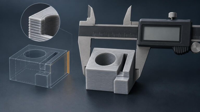
A CAD circle becomes a series of toolpaths with finite extrusion width and layer height. The resulting boundary is affected by how the slicer places those paths and how the deposited material spreads, cools, and bonds. Small deviations that are modest relative to an outside dimension can consume a meaningful share of a small opening.
Process settings also matter. A peer-reviewed investigation of material-extrusion hole accuracy examined layer thickness, print speed, shell count, orientation, slicer, printer, and material. Under its tested conditions, layer thickness had the greatest influence on diameter accuracy, followed by shell count around the holes. Those rankings and favorable settings belong to that experiment, not to every printer and profile. The published hole-accuracy study is useful evidence that hole error is a process-dependent result rather than a universal offset.
Excess extrusion can narrow the opening
If too much material is deposited, perimeter lines can occupy more space than intended and reduce the available bore. Look beyond the hole: swollen outside walls, crowded details, rough perimeter buildup, or several tight mating features suggest a broader extrusion problem rather than a hole-only error.
Prusa describes the extrusion multiplier as the control used to tune filament output and identifies excess material buildup as overextrusion. It also notes that the suitable multiplier can vary with material, color, and even spool; its calibration method depends on nozzle size, extrusion width, and layer height. That is why copying a flow value from another machine is not a reliable hole fix.
First-layer squish can create a tight lower lip
If a vertical hole is correct through most of its height but tight at the build-plate entrance, inspect the first few layers. Excessive first-layer squish pushes geometry outward. On an outside edge this appears as a wider base; inside a hole, the same deformation intrudes into the opening.
Prusa documents Elephant Foot Compensation as a slicer setting that shrinks first-layer geometry. Its documentation gives about 0.2 mm as a common starting point for a default 0.4 mm nozzle setup, but that is a profile-specific starting point—not a general hole allowance. Correct first-layer setup before applying aggressive compensation, or add a small designed chamfer when the entrance edge does not need to remain square.
Horizontal holes have a different geometry problem
A hole printed with its axis parallel to the build plate is built from overhangs. The upper arc may sag or flatten because each new line has limited support beneath it. The resulting opening can be undersized vertically even when its width is close to nominal.
Do not treat this as the same problem as a uniformly small vertical bore. Better options may include changing the part orientation, adding support where surface cleanup is acceptable, redesigning the opening with a self-supporting upper profile, or leaving stock for drilling. Rotating the part can solve the bore while weakening another feature, so evaluate loads and mating surfaces before changing orientation.
Read the error pattern before changing settings
| Observed result | Likely area to investigate | First useful check |
|---|---|---|
| Uniformly small vertical hole | Repeatable hole-path or extrusion error | Compare several bore sizes and check whether outside dimensions are also oversized. |
| Tight only at the build-plate edge | First-layer squish or elephant foot | Inspect the lower layers and test first-layer correction or an entry chamfer. |
| Outside dimensions and holes are both wrong | Scaling, motion, extrusion, or general dimensional calibration | Measure a controlled test part in X and Y before applying hole-only compensation. |
| Hole is oval | Directional motion, geometry, cooling, or measurement issue | Measure across X and Y separately and repeat the print in a controlled orientation. |
| Sideways hole has a flat or sagging top | Unsupported upper arc | Change orientation or use a self-supporting profile. |
| Different hole sizes show different errors | Feature-size-dependent process behavior | Print a multi-size coupon rather than deriving one offset from one bore. |
This pattern-based approach prevents one setting from masking another fault. If all dimensions are incorrect, use a broader dimensional accuracy calibration workflow before tuning individual holes. Hole-specific compensation should be reserved for a consistent hole-specific error.
Run a controlled hole-coupon test
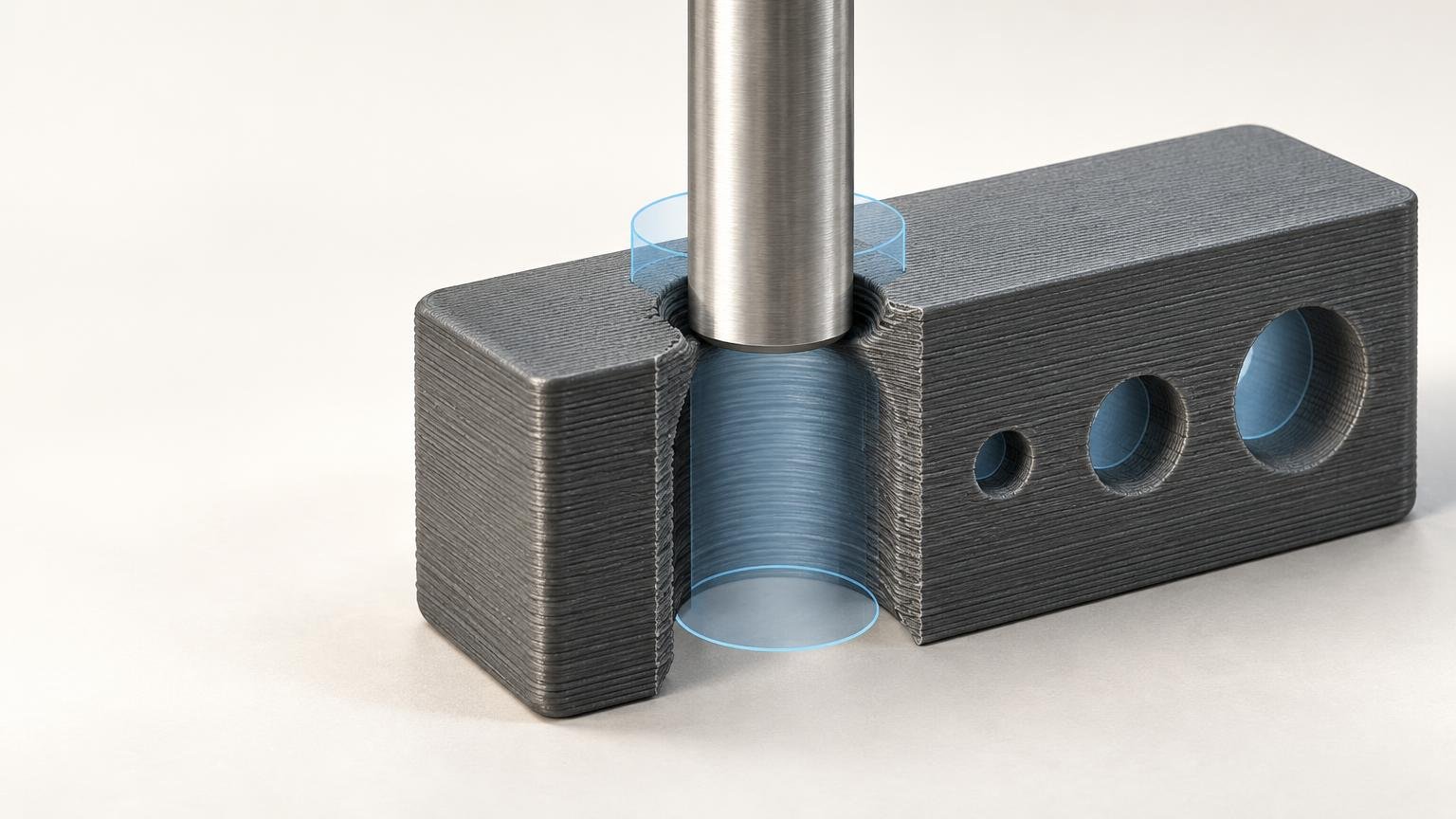
A useful coupon contains several nominal bore sizes spanning the features in the final part. Use the same conditions that matter to the production print. Changing the filament, orientation, layer height, or wall configuration between the coupon and final part weakens the comparison.
- Record the printer, nozzle diameter, filament material and spool, layer height, orientation, wall count, temperature, cooling, speed profile, and slicer version.
- Include at least the actual hole sizes needed by the design. Add repeated holes when repeatability matters.
- Print the coupon in the same orientation and with the same profile planned for the functional part.
- Allow it to cool before measuring. Remove only loose debris; do not unknowingly enlarge the bore during cleanup.
- Measure each opening in more than one direction when practical. Record nominal diameter, measured diameter, roundness differences, and entry-edge condition.
- Test the actual fastener, pin, shaft, bearing, or tool. Record pass, bind, excessive play, or insertion force in terms meaningful to the assembly.
- Change one relevant variable, reprint, and confirm that the correction remains repeatable.
Keep the measurement method consistent. Calipers may be adequate for larger accessible bores, but small internal dimensions can be sensitive to jaw shape and contact angle. Gauge pins, known drill shanks, or the actual mating component can provide a more decisive functional check. Do not claim more precision than the measuring method can resolve.
Choose the narrowest correction that solves the problem
Correct broad extrusion or machine errors first
If excess material affects outside walls, slots, and several mating features, verify extrusion behavior and general dimensional accuracy before editing every CAD hole. Also inspect belt condition, pulley security, axis motion, and whether X and Y errors differ. A hole offset cannot make an oval or mechanically inconsistent printer accurate.
Fix the first layer when only the entrance is tight
For a lower-edge lip, correct nozzle-to-bed setup and first-layer behavior first. Use slicer elephant-foot compensation cautiously, or add a small chamfer to the bottom edge when the design permits it. Enlarging the complete bore wastes clearance in the section that was already correct.
Use hole-specific slicer compensation for repeatable errors
When vertical holes are consistently undersized but outside dimensions are acceptable, a hole-specific slicer adjustment can be more targeted than scaling the complete model. Cura’s official setting definitions include Horizontal Expansion and Hole Horizontal Expansion, plus a maximum-diameter control intended to keep small-hole compensation from changing larger holes. Names and availability can vary with the installed Cura release and printer profile, so verify the controls in your version.
Begin with a measured coupon result, apply a modest correction, and print again. Do not assume the required adjustment equals the full measured diameter error without validation; toolpath generation and neighboring walls can make the response differ from a simple one-to-one calculation.
Change CAD when the allowance belongs to the design
A CAD allowance is appropriate when the part will repeatedly be produced with a controlled process and the hole’s functional requirement is known. Document the intended nominal mating component and validated process allowance. Avoid silently changing a standard fastener size without recording why, because a later material or profile change may require a different value.
Drill or ream critical bores
Post-processing is often the cleaner engineering choice for a bore that must closely locate a shaft, accept a bearing predictably, or align an assembly. Print the opening deliberately undersize, provide enough surrounding material, and bring it to final size with the appropriate drill or reamer. Consider how the part will be held and supported so the finishing operation does not split layers or pull the tool off-axis.
Common questions
Should I enlarge the hole in CAD or in the slicer?
Use slicer compensation when a known printer and profile produce a repeatable hole-specific error across suitable models. Use a documented CAD allowance when the adjustment is an intentional requirement of that part and manufacturing process. First correct broad calibration, first-layer, or orientation problems that would make either allowance unstable.
Why do smaller holes need separate testing?
The same absolute intrusion consumes a larger proportion of a small opening, and slicer toolpaths can change as features approach extrusion-width limits. Test the sizes you will actually use instead of extrapolating from one large bore.
Why is my hole oval instead of simply undersized?
An oval result means the error differs by direction. Check X and Y measurements separately, then inspect motion, orientation, unsupported geometry, and the way the hole was measured. Uniform diameter compensation is unlikely to fix a directional fault.
Can I use one compensation value for every material?
Not responsibly without validation. Material, spool, nozzle, layer height, wall configuration, orientation, extrusion tuning, and slicer profile can all change the result. Even extrusion-multiplier guidance recognizes variation between materials, colors, and spools.
Prove the fit, not just the diameter
The best next step is a same-profile hole coupon followed by a test with the real mating component. Determine whether the error is uniform, confined to the first layer, directional, or caused by a horizontal overhang. Then make one targeted correction: calibrate a broad process error, control elephant foot, change orientation or geometry, apply measured hole compensation, or finish the bore mechanically.
A successful correction is not the offset that makes one caliper reading look right. It is the smallest controlled change that produces the required fit repeatedly under the same documented printing conditions.