
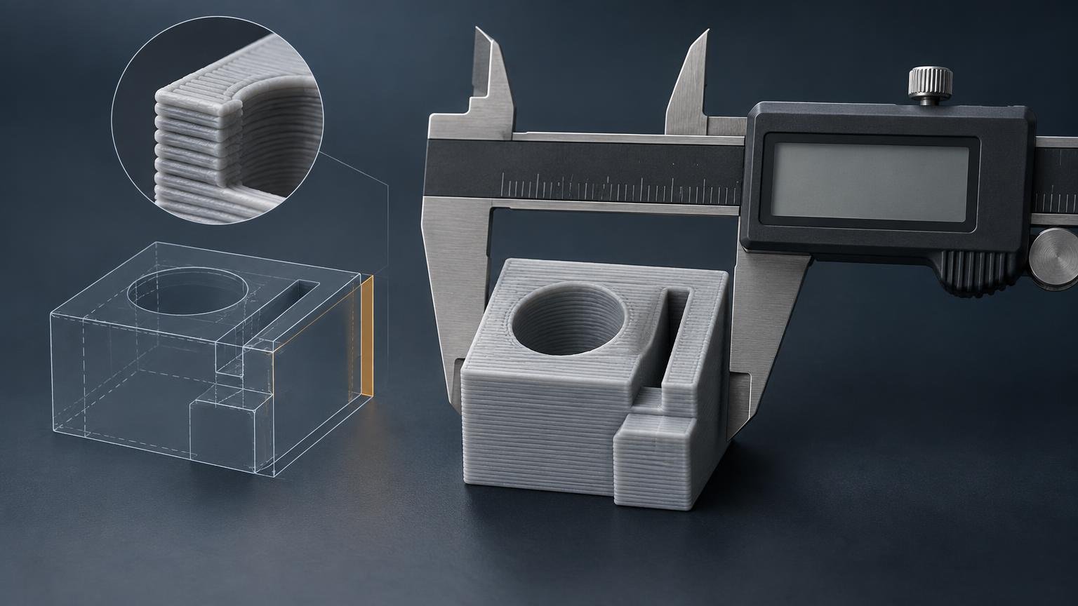
TLDR: To learn how to calibrate dimensional accuracy on an fdm printer, define the critical feature and its acceptable tolerance, stabilize the print conditions, calibrate material flow, print a feature-based test, measure it after cooling, and correct only the error pattern you can demonstrate. Finish by printing the real interface and checking whether it fits and functions repeatedly.
A calibration cube can reveal a broad problem, but it cannot prove that a bore accepts a bearing, a pin slides freely, or two printed parts assemble. Dimensional calibration succeeds when the cooled part meets its specified dimensions and functional requirement—not when one convenient cube happens to read close to nominal.
Define what counts as dimensionally accurate
Start with the feature that matters. Record its nominal CAD dimension, allowable deviation, feature type, measurement direction, and functional requirement. A shaft diameter, hole diameter, center-to-center spacing, overall width, and Z height can respond differently even when they appear in the same model.
For example, “the part should be accurate” is not a usable acceptance rule. “This bore must accept the intended insert without splitting the wall” is useful. Better still, pair that fit requirement with a drawing dimension and permitted range. The actual mating component can serve as a functional gauge, but dimensional measurements help explain why a fit passed or failed.
Do not choose a tolerance merely because a caliper displays two decimal places. The measuring tool, printed surface texture, part flexibility, and measurement technique must all be capable of distinguishing a pass from a failure. If your requirement is tighter than your measurement process can resolve reliably, improve the measurement method or reconsider the requirement before changing the printer.
How to calibrate dimensional accuracy on an FDM printer
Use a controlled sequence rather than changing several slicer and firmware settings at once. The practical order is: stabilize the machine and first layer, establish a material-specific flow setting, test representative geometry, diagnose the error pattern, apply the narrowest correction, and validate the real part.
1. Hold the printing conditions constant
Choose one printer, nozzle, material spool, slicer profile, layer height, temperature set, cooling strategy, speed profile, and part orientation. Record them with the result. Changing filament or rotating the model while evaluating a correction makes it difficult to tell whether the setting actually helped.
Measure parts only after they have cooled under a consistent condition. UltiMaker’s FFF design guidance identifies material shrinkage as a dimensional consideration and recommends printing and measuring test parts against the original design when exact dimensions matter. A measurement taken hot is therefore not interchangeable with one taken after cooling.
2. Rule out basic machine and first-layer faults
Inspect the printer before compensating for its output in software. Look for looseness, binding, debris on motion components, damaged wheels or bearings, loose pulleys, inconsistent belt condition, poor gantry alignment, or a nozzle that is not secure. Use the printer manufacturer’s procedure for mechanical checks because the correct belt tension, fastener arrangement, and calibration routine depend on the machine.
Confirm that the first layer is repeatable. Excessive first-layer compression can make the bottom of a part wider than the geometry above it. If only the base is oversized, changing compensation for the entire model can improve the bottom while making the rest undersized. Correct the first-layer setup or use an appropriate bottom-edge treatment instead.
Avoid changing X-, Y-, or Z-axis scaling from a single small cube. A local bulge, first-layer flare, flow error, measurement mistake, or cooling distortion can resemble a scale error. Consider axis calibration only when a repeatable error accumulates with distance, appears across suitable test geometries, and remains after mechanical and extrusion issues have been addressed. Follow the documentation for the printer and firmware before altering motion parameters.
3. Calibrate extrusion flow for the material profile
Extrusion flow affects the width and position of printed walls. Too much deposited material can enlarge external boundaries, constrict openings, and exaggerate corner artifacts. Too little can produce thin walls, gaps, or weak bonding. Flow calibration should come before broad dimensional compensation because compensation can otherwise hide an incorrect material-delivery setting.
Prusa documents a single-wall method that compares commanded extrusion width with average measured wall thickness. Its calculation uses commanded width divided by measured thickness to derive a revised extrusion multiplier. The same documentation recommends measurements at three or more locations and warns that inexpensive calipers may be unreliable for a single perimeter wall. Follow the exact geometry and slicer conditions specified by the workflow you select rather than mixing dimensions from unrelated tutorials.
Treat the result as material-profile-specific. Prusa notes that the appropriate extrusion multiplier can vary with material type, color, and individual spool. Save the calibrated value with a traceable profile name that identifies the material, spool or batch where practical, nozzle, and relevant print conditions.
4. Print a test that represents the real features
Once flow is stable, use a compact test piece containing the kinds of geometry found in the real part. A useful test may combine an external X dimension, an external Y dimension, circular holes, pins, center spacing, a taller Z feature, and a stepped fit ladder. You do not need every feature in every test; include the ones that control the intended assembly.
Keep the test large enough to measure without excessive influence from surface texture, but economical enough to reprint after each meaningful change. Include labels or unmistakable geometry so the X and Y directions cannot be confused. If build orientation is flexible in the final design, print the test in the candidate orientations rather than assuming they are equivalent.
Orientation deserves explicit validation. A study using coordinate measuring and 3D-scanning methods reported orientation-dependent dimensional variation for its tested machines, parts, materials, and metrology setup. Its exact results should not be generalized to every printer, but it supports treating orientation as a test condition rather than a neutral choice. Readers interested in the metrology can review the dimensional repeatability study.
5. Measure error and repeatability separately
For each feature, record the nominal dimension, each measured value, the measurement direction, and the signed error. Use: signed error = measured dimension − nominal dimension. A positive result means the measured feature is larger; a negative result means it is smaller.
Take repeated readings at defined positions. For an external width, measure away from a swollen first layer and obvious seam artifacts unless those regions are part of the functional interface. For a hole, measure in more than one direction. A circular opening that reads differently along X and Y is not simply “undersized”; it may be oval, distorted, or affected by direction-specific motion behavior.
Also separate bias from variation. If repeated prints are consistently too large by a similar amount, a targeted compensation may help. If nominally identical prints scatter between too large and too small, compensation is unlikely to solve the underlying instability. Investigate mechanics, thermal conditions, filament delivery, bed location, and measurement repeatability first.
Match the correction to the error pattern
| Observed pattern | Likely area to investigate | Preferred response |
|---|---|---|
| Most exterior XY dimensions are consistently biased | Flow, cooling shrinkage, or broad XY behavior | Verify flow and mechanics, then test a small profile-level compensation on the same geometry. |
| Holes are undersized while exterior dimensions pass | Hole geometry, extrusion path, cooling, or feature-specific behavior | Use a hole-specific slicer adjustment or CAD allowance validated for that hole range and orientation. |
| Only the bottom edge is oversized | First-layer compression or bottom flare | Correct the first layer or apply a bottom-edge correction instead of changing the whole part. |
| Corners bulge but straight wall sections pass | Pressure during speed changes | Tune pressure-management or speed-transition behavior and retest corners. |
| X and Y differ, or circles are oval | Direction-specific mechanics, alignment, or motion behavior | Inspect the machine and test both axes before applying compensation. |
| Error increases with part height | Z motion, thermal distortion, or true scale behavior | Test multiple heights and follow machine-specific mechanical and firmware procedures. |
| Dimensions change with orientation | Cooling, support contact, layer geometry, or anisotropic process behavior | Select and document the orientation that meets the real requirement. |
Corner bulges deserve their own diagnosis. Prusa’s pressure-equalizer documentation describes bulging on external perimeters when extruder pressure remains excessive through speed changes, and it identifies pressure and speed-transition management as ways to improve the result. Reducing every external dimension to compensate for bulged corners would make straight sections smaller while leaving the underlying transition problem unresolved.
Likewise, do not assume one compensation value will fix external dimensions, bores, pins, and spacing equally. A broad horizontal-size adjustment moves many boundaries, while a hole-specific allowance targets an internal feature. CAD allowance may be the most controlled option when one interface requires a deliberate fit and the rest of the model already passes.
Validate the correction instead of trusting the setting
After making one justified change, reprint the same test with the same conditions. Compare the new signed error and variation with the baseline. A correction passes only if it improves the target feature without pushing other critical features outside their permitted ranges.
Then print the actual interface. Measure it after cooling and test it with the real mating part, fastener, bearing, insert, gauge, or adjacent printed component. Cycle moving fits more than once where wear-in, binding, or assembly force matters. A nominally correct dimension can still fail because of surface ridges, seam placement, ovality, or local deformation.
Save enough information to reproduce the result: printer, nozzle, material and spool, slicer and profile, layer height, temperatures, cooling, speeds, orientation, test model revision, measuring tool, measurements, correction applied, and final pass or fail result. This turns a lucky print into a usable process.
The practical next step
Choose one critical feature from the real part and write its pass condition before printing anything else. Calibrate material flow, produce a representative test in the intended orientation, measure it after cooling, and classify the error pattern. Make the narrowest correction that addresses that pattern, then repeat the same test and confirm the actual fit.
Dimensional accuracy is not a single permanent number attached to the printer. It is a demonstrated result for a particular machine, material profile, geometry, orientation, and measurement method. The calibration is finished when the part repeatedly meets the requirement that matters.